在使用很多API服務像是Google的API或是Facebook的API, 常常會需要拿簽署APK的Key的signature登錄, 取得這sigature的方法有很多種, 剛學到一種是直接可以從Android studio的Gardle選單內取得的, 方法如下:
Gradle->(Project name)->Tasks->singningReports
在使用很多API服務像是Google的API或是Facebook的API, 常常會需要拿簽署APK的Key的signature登錄, 取得這sigature的方法有很多種, 剛學到一種是直接可以從Android studio的Gardle選單內取得的, 方法如下:
Gradle->(Project name)->Tasks->singningReports
WebRTC是一個支援瀏覽器的即時影音對話的架構, 算是一個業界標(W3C,IETF), 最近由於想做一個有影音通話的應用, 就研究了一下這東西
如果只是想嘗試一下WebRTC, 是可以直接是可以直接試AppRTC這個Google的範例, 不過這個是Web的版本, 我想要做的是 手機的版本(Android, iOS), AppRTC其實也有Android的版本可搭配
為了熟悉一下整個用WebRTC建立video call的流程, 因此我就決定改一下這個Android版本, 原本Google的版本是透過Web Socket
至於流程與架構我會建議看這影片:
如果不想看太長, 就看這個:
把Web RTC那段換成Firebase(好, 其實我蠻後悔選Firebase來實作的)其實就是把Signaling這段給換掉, 而這段流程是(節錄自影片):
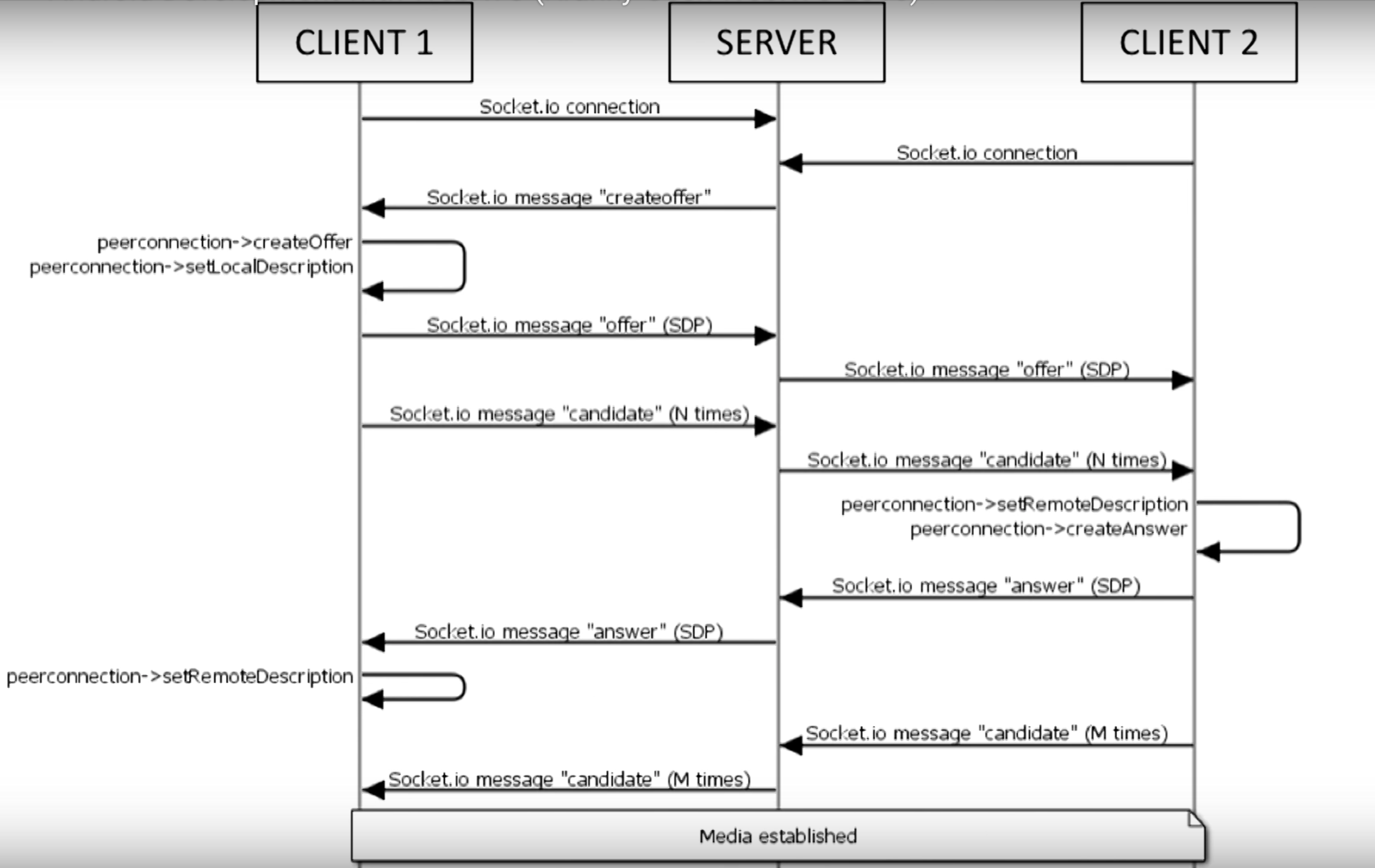
這部分其實就是交換兩邊的SDP和ICE candidate的過程, 詳細可以參考這邊:WebRTC 相關縮寫名詞簡介
結果的source code放在這邊 : apprtc-android-demo
其實現在寫WebRTC的應用的話, 也不用從頭實作, Google老早就把它實作在Chromium裡面了, 也可以單獨build出library用
這邊有官方的如何建置出Android版本的Web RTC library, 不過, 不要照著這份文件做呀, 不然頭髮會白好幾根, 可能還build不太起來, 找了一堆網路上人家的建議也都是不要直接build, 直接用人家build好現成的, 不過, 現成的雖然有一些, 但大多是過時的, API跟現今的也不太一樣, 如果 要套用到現在的Android版本AppRTC的source code內, 大多都沒辦法用
所幸找到這個build script: pristineio/webrtc-build-scripts, 這個從下載最新的source code到build出library一律包辦, 用法也很簡單, 只要執行下面的:
source android/build.sh
install_dependencies
get_webrtc
build_apprtc
簡單明暸, 但…有幾個問題, 第一個是只能在Linux下build, 因此在Mac跟Windows下要透過Vagrant這類的工具, 而且對硬體需求也很高, 我的2012年中版的Macbook Pro retina實在是跑不動, 後來跑去Digital Ocean租了台VM來build, 本以為最便宜的可以勝任, 後來發現, 至少要4G RAM, 硬碟要20G以上的instance(哭哭, 浪費好多時間)
build出來後, 所需要的東西包含了libjingle_peerconnection.jar和libjingle_peerconnection_so.so, 把這幾個備份起來就是了, 待會build apk需要用
Android的範例的source codes可以在這邊下載
不過這並不是Android studio的project格式, 因此需要用匯入的方式, 或是可以直接fork我的版本去改, 由於原本的版本使用了Web socket做singaling的管道, 因此需要Autobahn, 但你切記絕對不能用Autobahn官方最新的jar檔, 而是要用Google放在third_party裡面那個autobanh.jar(啊, 我到現在才發現名字有些許不同), 這邊的差異是, 原本Autobahn是沒有支援SSL的websocket的, 但AppRTC的websocket則是要透過SSL來連接
把jar跟so檔放到對應的目錄去後, 記得改一下app目錄下的build.gradle加入 (因為import產生的不會幫你加):
dependencies {
    compile fileTree(dir: 'libs', include: ['*.jar'])
}
除了原本的Webcoket和Direct connect兩種方式外, 為了跑一次他的流程我多加了Firebase的部分, 利用它的realtime database來做Signaling這部分, 至於怎樣開始開發firebase, 就參考一下他的官方文件吧
選擇哪種signaling的方式是在CallActivity裡面依據roomId來看使用哪一個signaling client, 程式碼如下:
    // Create connection client. Use DirectRTCClient if room name is an IP otherwise use the
    // standard WebSocketRTCClient.
    if("firebase".equals(roomId)) {
      Log.d(TAG, "firebase");
      appRtcClient = new FirebaseRTCClient(this);
    } else if (loopback || !DirectRTCClient.IP_PATTERN.matcher(roomId).matches()) {
      appRtcClient = new WebSocketRTCClient(this);
    } else {
      Log.i(TAG, "Using DirectRTCClient because room name looks like an IP.");
      appRtcClient = new DirectRTCClient(this);
    }
原本有WebSocketRTCClient和DirectRTCClient, 如果是IP的話就用DirectRTCClient,這邊我多加一個FirebaseRTCClient, 只要roomId是firebase就會使用這個(我偷懶)
XXXRTCClient這部分實作了signaling的部分, 因此我參考了WebSocketRTCClient和DirectRTCClient的內容來寫FirebaseRTCClient
跟WebSocketRTCClinet一樣, 它必須實作AppRTCClient, AppRTCClient這個Interface定義如下:
/**
 * AppRTCClient is the interface representing an AppRTC client.
 */
public interface AppRTCClient {
  /**
   * Struct holding the connection parameters of an AppRTC room.
   */
  class RoomConnectionParameters {
    public final String roomUrl;
    public final String roomId;
    public final boolean loopback;
    public RoomConnectionParameters(String roomUrl, String roomId, boolean loopback) {
      this.roomUrl = roomUrl;
      this.roomId = roomId;
      this.loopback = loopback;
    }
  }

  /**
   * Asynchronously connect to an AppRTC room URL using supplied connection
   * parameters. Once connection is established onConnectedToRoom()
   * callback with room parameters is invoked.
   */
  void connectToRoom(RoomConnectionParameters connectionParameters);

  /**
   * Send offer SDP to the other participant.
   */
  void sendOfferSdp(final SessionDescription sdp);

  /**
   * Send answer SDP to the other participant.
   */
  void sendAnswerSdp(final SessionDescription sdp);

  /**
   * Send Ice candidate to the other participant.
   */
  void sendLocalIceCandidate(final IceCandidate candidate);

  /**
   * Send removed ICE candidates to the other participant.
   */
  void sendLocalIceCandidateRemovals(final IceCandidate[] candidates);

  /**
   * Disconnect from room.
   */
  void disconnectFromRoom();

  /**
   * Struct holding the signaling parameters of an AppRTC room.
   */
  class SignalingParameters {
    public final List<PeerConnection.IceServer> iceServers;
    public final boolean initiator;
    public final String clientId;
    public final String wssUrl;
    public final String wssPostUrl;
    public final SessionDescription offerSdp;
    public final List<IceCandidate> iceCandidates;

    public SignalingParameters(List<PeerConnection.IceServer> iceServers, boolean initiator,
        String clientId, String wssUrl, String wssPostUrl, SessionDescription offerSdp,
        List<IceCandidate> iceCandidates) {
      this.iceServers = iceServers;
      this.initiator = initiator;
      this.clientId = clientId;
      this.wssUrl = wssUrl;
      this.wssPostUrl = wssPostUrl;
      this.offerSdp = offerSdp;
      this.iceCandidates = iceCandidates;
    }
  }

  /**
   * Callback interface for messages delivered on signaling channel.
   *
   * <p>Methods are guaranteed to be invoked on the UI thread of |activity|.
   */
  interface SignalingEvents {
    /**
     * Callback fired once the room's signaling parameters
     * SignalingParameters are extracted.
     */
    void onConnectedToRoom(final SignalingParameters params);

    /**
     * Callback fired once remote SDP is received.
     */
    void onRemoteDescription(final SessionDescription sdp);

    /**
     * Callback fired once remote Ice candidate is received.
     */
    void onRemoteIceCandidate(final IceCandidate candidate);

    /**
     * Callback fired once remote Ice candidate removals are received.
     */
    void onRemoteIceCandidatesRemoved(final IceCandidate[] candidates);

    /**
     * Callback fired once channel is closed.
     */
    void onChannelClose();

    /**
     * Callback fired once channel error happened.
     */
    void onChannelError(final String description);
  }
}
主要就是定義了如何處理connect, disconnect, 還有怎麼去註冊SDP和ICE candidate, 在確定好連接成功後, AppRTCClient要負責呼叫onConnectedToRoom來通知 CallActivity已經可以準備建立video call的後續流程, 且要負責處理如果Signal server(這邊是firebase)有傳來遠端的SDP跟ICE candidate, 要負責呼叫SignalingEvents對應的處理 (這邊一樣會叫到CallActivity, 而CallActivity則會使用PeerConnectionClient來處理需要傳遞給PeerConnection相關的參數)
這邊用Firebase處理Signaling的方式是監聽某一個key的改變, 有新的裝置連接, 註冊SDP, ICE Candidate, 就寫到這下面去, 這其實不是一個很好的方式, 因為這下面只要有值的改變, 就會觸發, 不像是WebSocket那個版本是一來一往的API calls, 而且你不知道每次觸發被更動的是哪一部分, 一開始發生了好幾次PeerConnection重複註冊SDP才讓我發現因為這原因被重複呼叫的問題
WebRTC是P2P的, 因此如果不具備穿牆能力的話, 在牆外就會被擋掉, 一開始我本來想說試驗P2P而不走TURN Server穿牆的(因為我一時也懶得架一台), 結果測試時老是連不上, 後來才發現我阿呆, 我的測試環境是一台實體手機, 另一台是電腦上跑模擬器, 本以為兩個(手機, 電腦)是同一個區網沒問題, 後來才想到模擬器是在另一個虛擬網路, 因此還是有需要TURN server
如果不想架一台, 要怎辦? 用Google免錢的, 他們做了這個demo, 一定有! 因此就偷看了一下WebRTCClient的code跟傳輸內容,發現它跟https://networktraversal.googleapis.com/v1alpha/iceconfig?key=AIzaSyAJdh2HkajseEIltlZ3SIXO02Tze9sO3NY 去要TURN server list, 所以基本上只要照copy下面這段就好:
   private LinkedList<PeerConnection.IceServer> requestTurnServers(String url)
            throws IOException, JSONException {
        LinkedList<PeerConnection.IceServer> turnServers = new LinkedList<PeerConnection.IceServer>();
        Log.d(TAG, "Request TURN from: " + url);
        HttpURLConnection connection = (HttpURLConnection) new URL(url).openConnection();
        connection.setDoOutput(true);
        connection.setRequestProperty("REFERER", "https://appr.tc");
        connection.setConnectTimeout(TURN_HTTP_TIMEOUT_MS);
        connection.setReadTimeout(TURN_HTTP_TIMEOUT_MS);
        int responseCode = connection.getResponseCode();
        if (responseCode != 200) {
            throw new IOException("Non-200 response when requesting TURN server from " + url + " : "
                    + connection.getHeaderField(null));
        }
        InputStream responseStream = connection.getInputStream();
        String response = drainStream(responseStream);
        connection.disconnect();
        Log.d(TAG, "TURN response: " + response);
        JSONObject responseJSON = new JSONObject(response);
        JSONArray iceServers = responseJSON.getJSONArray("iceServers");
        for (int i = 0; i < iceServers.length(); ++i) {
            JSONObject server = iceServers.getJSONObject(i);
            JSONArray turnUrls = server.getJSONArray("urls");
            String username = server.has("username") ? server.getString("username") : "";
            String credential = server.has("credential") ? server.getString("credential") : "";
            for (int j = 0; j < turnUrls.length(); j++) {
                String turnUrl = turnUrls.getString(j);
                turnServers.add(new PeerConnection.IceServer(turnUrl, username, credential));
            }
        }
        return turnServers;
    }

    // Return the contents of an InputStream as a String.
    private static String drainStream(InputStream in) {
        Scanner s = new Scanner(in).useDelimiter("\\A");
        return s.hasNext() ? s.next() : "";
    }
把這邊拿來的list當ICE candidate, 就可以成功透過Google的TURN server去穿牆了(長久之計還是自己架一台吧)
小時候很喜歡Indiana Jones系列的電影, 對於它裡面的地圖片段也一直覺得很有趣
如果這樣的動畫, 用在遊記類的blog上, 應該也蠻酷的, 但好像也沒一個比較好的工具, 因此想說用MapKit來實作一個試試
先來定義一個簡單的功能需求
這部份要用到MKGeodesicPolyline, 給它兩個點, 它就會自動連結成一條線, 但這條線並不是完美的直線, 因為地球表面是曲面的, 所以它是一條弧線
let coords = [start, end]

geodesicPolyline = MKGeodesicPolyline(coordinates: coords, count: 2)

print(geodesicPolyline!.pointCount)
mapView.add(geodesicPolyline!)
這邊coors只要給訂起始點跟終點的位置就好, 印出pointCount就會發現它把經由的點都補足了(實際上印出來的會多出2很多很多)
MKGeodesicPolyline裡的參數coordinates是一個UnsafeMutablePointer, 在Swift 3之前要寫成&coords, 但在Swift 3大改之後, “&“就不需要了
由於MKGeodesicPolyline是一個Overlay, 因此最後只需要用mapView.add (Swift 3之前是addOverlay)加入mapView就可以了, 但加入之後, 會發現, 這條線根本沒被畫出來, 那是因為少寫了一部分
在MapView裡面要畫出Overlay, 就必須要跟MapView說怎麼畫出這個Overlay, 這就要實作MKMapViewDelegate裡的mapView(_ mapView: MKMapView, rendererFor overlay: MKOverlay)
func mapView(_ mapView: MKMapView, rendererFor overlay: MKOverlay) -> MKOverlayRenderer {
    guard let polyline = overlay as? MKPolyline else {
        return MKOverlayRenderer()
    }

    let renderer = MKPolylineRenderer(polyline: polyline)
    renderer.lineWidth = 3.0
    renderer.alpha = 0.5
    renderer.strokeColor = UIColor.blue

    return renderer
}
由於我們是要畫Poly line, 因此這邊回傳給它一個MKPolylineRenderer, 線寬是3.0, 線的顏色是藍色(alpha = 0.5)
這樣就可以很完美的畫出那條線了
這部份就要借重到MKPointAnnotation
let thePlane = MKPointAnnotation()
thePlane.coordinate = start //給定起始座標

mapView.addAnnotation(thePlane)
一樣, 這邊如果沒告訴MapView怎畫這Annotation, 它是會用預設的取代, 因此我們一樣要去實作MKMapViewDelegate
func mapView(_ mapView: MKMapView, viewFor annotation: MKAnnotation) -> MKAnnotationView? {
    let planeIdentifier = "Plane"

    let annotationView = mapView.dequeueReusableAnnotationView(withIdentifier: planeIdentifier)
        ?? MKAnnotationView(annotation: annotation, reuseIdentifier: planeIdentifier)

    annotationView.image = UIImage(named: "ic_flight_48pt")

    return annotationView
}
這邊用一個UIImage來指定飛機的圖標
把飛機置於地圖正中央, 我們才看得到他, 因此, 需要設定可視的區域, 包含中心點跟範圍, 如下:
let span = MKCoordinateSpanMake(8.0, 8.0)
let region1 = MKCoordinateRegion(center: start, span: span)
self.mapView.setRegion(region1, animated: true)
這時候要利用到 perform(#selector(updatePlane), with: self, afterDelay: 0.4) 讓它每隔0.4秒去更新一次飛機位置, 直到到終點為止, 當然也要一直更新region, 以讓飛機維持在正中央
func updatePlane() {
    planePositionIndex = planePositionIndex + step;

    if (planePositionIndex >= geodesicPolyline!.pointCount)
    {
        //plane has reached end, stop moving
        planePositionIndex = 0
        return;
    }

    let s = 8.0

    let nextMapPoint = geodesicPolyline?.points()[planePositionIndex]

    thePlane.coordinate = MKCoordinateForMapPoint(nextMapPoint!)
    mapView.region = MKCoordinateRegionMake(thePlane.coordinate, MKCoordinateSpan(latitudeDelta: s, longitudeDelta: s))

    perform(#selector(updatePlane), with: self, afterDelay: 0.4)
}
這邊有幾個缺點尚待改進
最近直播蠻火紅的, 直播服務也不少, 連Facebook都做了直播功能, 最近也跟人聊了不少這方面的東西, 所以想說趁中秋連假來自己研究看看, 只是中秋節連假雖然多, 做的事情還真是不少, 看電影, 打球, 打電動, 看球的, 又碰上颱風天, 不過還是先搞個簡單的雛形唄
市面上有不少關於直播的應用, 應該說, 簡直是氾濫, 而且每一種人氣似乎都是很旺, 還不是很了解在旺啥的, 現在可能也不少人認為當個網紅就可以一炮而紅之類的




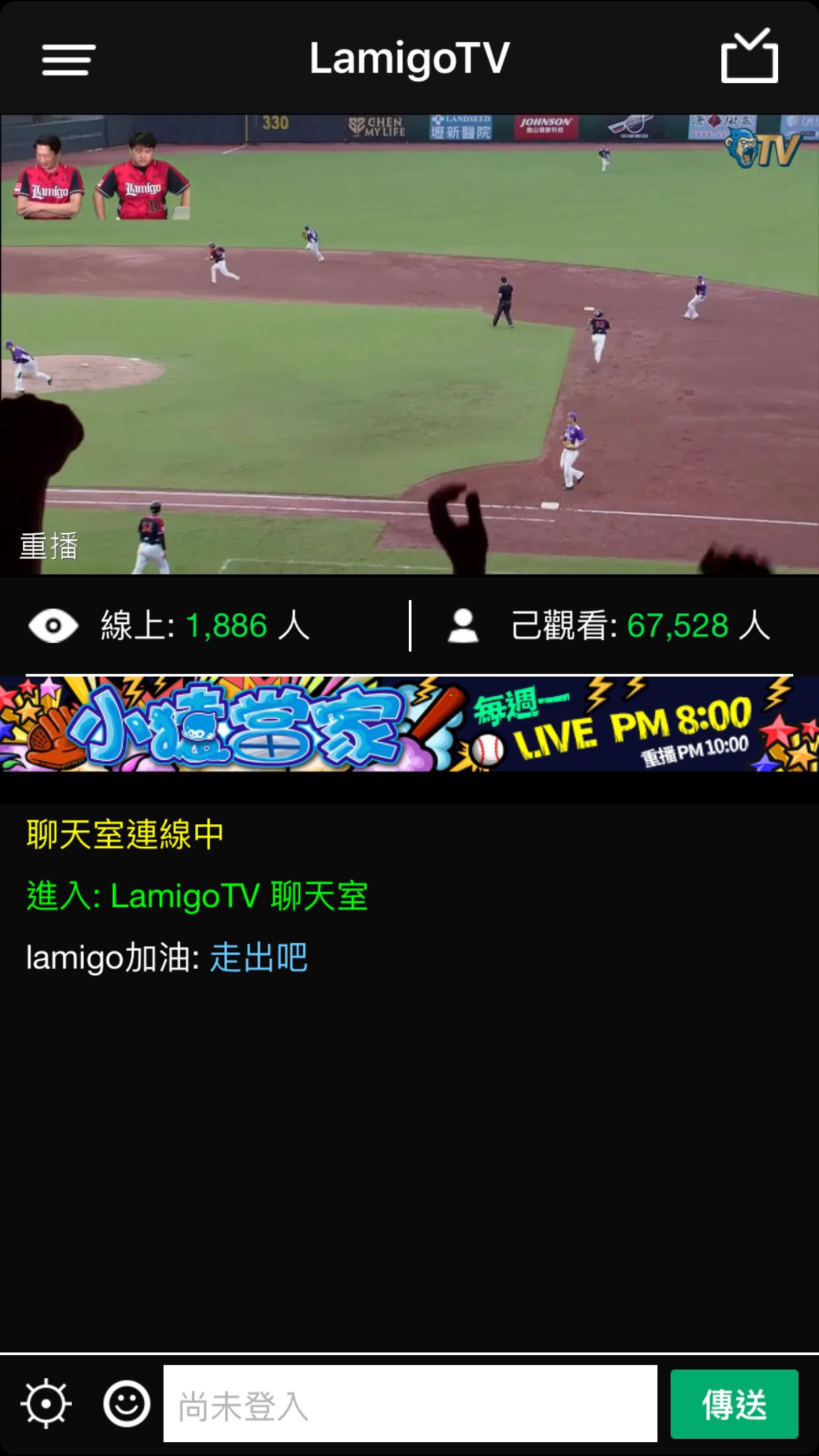
這邊其實可以看出, 根本大同小異, 大多是賣肉…喔, 不是, 賣網紅, 後面故意舉了一個麥卡貝當例子, 它是稍微不一樣, 以賣直播節目像是運動比賽的轉播(嗚~~金鋒退休了). 而不是一般的UGC(User generated), 當然這邊也沒舉一般很流行的遊戲直播像是Twitch, 不過這類早已為大家所熟知了
不管是哪一種, 大部分的設計都是大同小異, 都是以單向直播為主, 輔以文字聊天室, 可以送個愛心或禮物, Facebook稍稍進階點, 會將直播過程錄製下來, 不只錄製節目, 還有過程中的互動, 不過大家都是蠻近似的
如果照以上的功能設計, 簡單的可以畫成兩個部分, 一個是直播串流(Video Stream)的部分, 一個則是聊天室的部分, 大致上的後端可以以這兩個為核心
關於直播串流的技術部分, Facebook 曾分享了一篇關於他們做直播串流經驗的文章:
Under the hood: Broadcasting live video to millions
從這邊可以了解到, 串流需要能夠支撐到非常多人同時觀賞, 網紅可能數百到數千, 像是蘋果的發表會, 或是Google I/O, WWDC 這種會議則可能是數萬到數十萬, 所以服務的高並發, 高流量是可以預期的, 架構上也要能夠承受這樣的強度, 簡化的畫起來應該像是這樣:
Viewer不直接從Media Server取串流內容是考量到Media server通常要接收多個Client發佈的串流, 一個假設性的想法是, 對於UGC(User generated content), 主播應該遠少於觀眾, 假設就算一個服務可以吸引到百萬級別的觀眾, 同時線上的主播應該了不起是幾千個而已, 即便如此, Media server本身從Client接收發布的串流資料後, 可能還需要做轉碼(transcoding), 和轉送的動作, 尤其是轉碼是較為耗CPU資源的工作, 如果把主播跟觀眾放在同一個伺服器上, 除了影響品質外, 也會不方便擴充, 因此減少Media server上的"觀眾"(讓觀眾只是其他少數的edge servers), 便可以在觀眾增加時相對好擴充容量(增加edge的數量)
但大部分的狀況來說, 每個直播的觀眾不一定是非常大量, 在Facebook那篇文章內也有提到, 在小量觀眾的狀況下, 分流到多個edge的效率應該就沒那麼的好了, 反而這時候放在同一台server減少延遲會是更好的選擇
串流的通訊協定有不少, 像是RTP, RTSP, RTMP, HLS, WebRTC等等, Facebook那篇文章主要提到的是RTMP, HLS, 查了一下資料, 似乎這兩個也是目前比較主流做直播用的, 雖然WebRTC被討論的也蠻多的, 但似乎比較沒被應用在大量的直播, RTMP跟HLS都是可以透過HTTP來做傳輸(RTMP需要做封裝 - RTMPT), 讓他們具有穿越防火牆的優勢, 而HLS是以檔案為基礎的, 所以適合用一般的CDN來做快取, 在做大量的直播優勢較大, 缺點是延遲太長了, 但這兩者其實也是可以合併使用的, 在小群體時用RTMP, 等觀眾成長到一定數量實再導流到HLS去
幾個初步的想法
發布
觀賞直播
這部分就沒什麼特別的了, 當一般的chat room做就好
這成品有點粗劣, 有點不好意思 :P
我publish client只實作iOS版本, 而Viewer只實作了Android版本(根本只各做一半嘛!!/翻桌), 後端用firebase處理資料的部分, 所以即時通知新的直播, 和聊天沒啥問題(但我聊天的UI還是沒刻 >"<)
既然沒有重新做輪子, 自然用了不少Open source的解決方案來達成, 從Server到Android, iOS要找到相關可用的實在不難, 可以說這部份實在是太成熟了, 研究完後覺得Facebook那篇文章也只是一般般而已
RTMP相關的解決方案還算不少, 這邊列幾個
硬體
我沒看到文件有寫硬體需求, 但我用Digital Ocean 1GB RAM, 30GB SSD的Droplet跑, 單一個直播, 直播好幾個鐘頭, CPU都不超過5%, 所以應該足夠
安裝
安裝上相當簡單
git clone https://github.com/ossrs/srs.gitgit checkout 2.0releasecd srs/trunk; ./configure ; make ;建置好的執行檔會在srs/trunk/objs目錄下, 可以直接執行
設定
conf目錄下有很多不同的設定檔可以參考, 因為我要試RTMP, HLS所以我用的設定檔如下:
listen              1935;
max_connections     1000;
srs_log_tank        file;
srs_log_file        ./objs/srs.log;
http_api {
    enabled         on;
    listen          1985;
}
http_server {
    enabled         on;
    listen          8080;
    dir             ./objs/nginx/html;
}
stats {
    network         0;
    disk            sda sdb xvda xvdb;
}
vhost __defaultVhost__ {
    hls {
        enabled         on;
		hls_fragment    10;
        hls_window      60;
        hls_path        ./objs/nginx/html;
        hls_m3u8_file   [app]/[stream].m3u8;
        hls_ts_file     [app]/[stream]-[seq].ts;
    }
}
相對應的設定可以參考文件
執行
很簡單: srs -c my.conf 即可
找到iOS支援RTMP publish的解決方案有幾種:
雖然文件上有提供cocoapods跟Carhtage的安裝方式, 但絕對不要用Carthage的那個, 第一原因是它Carthage支援似乎尚未搞定, 就算改點東西解決了它, 是可以安裝成功沒錯, 但會崩潰在XCGLogger, 似乎用framework含進來的方式會導致XCGLogger == nil, 這害我花了好多時間, 畢竟我是Carthage的愛用者, 後來轉用Cocoapods就沒事了
幾個需要加的部分:
AppDelegate.swift
func application(application: UIApplication, didFinishLaunchingWithOptions launchOptions: [NSObject: AnyObject]?) -> Bool {

        XCGLogger.defaultInstance().outputLogLevel = .Info
        XCGLogger.defaultInstance().xcodeColorsEnabled = true

        return true
    }
這兩行是設定logger要記錄的東西, 方便debug用
ViewController
override func viewDidLoad() {
	rtmpStream = RTMPStream(rtmpConnection: rtmpConnection)
    rtmpStream.syncOrientation = true
    rtmpStream.attachAudio(AVCaptureDevice.defaultDeviceWithMediaType(AVMediaTypeAudio))
        rtmpStream.attachCamera(DeviceUtil.deviceWithPosition(.Back))
    rtmpStream.addObserver(self, forKeyPath: "currentFPS", options: NSKeyValueObservingOptions.New, context: nil)

    rtmpStream.captureSettings = [
            "sessionPreset": AVCaptureSessionPreset1280x720,
            "continuousAutofocus": true,
            "continuousExposure": true,
        ]

    rtmpStream.videoSettings = [
            "width": 1280,
            "height": 720,
        ]
    lfView.attachStream(rtmpStream)

    view.addSubview(lfView)
}
直播的部分會跟他的LFView綁一起
後來選用LFLiveKit的原因不是因為他自帶美顏 :D, 他寫法跟lf.swift一樣簡單, 而且不一定要把preview加到UI裡面, 而且他的preview不用用特定的class,只要是UIView就可
範例直接貼他文件裡的就很清楚了:
// import LFLiveKit in [ProjectName]-Bridging-Header.h
import <LFLiveKit.h>

//MARK: - Getters and Setters
lazy var session: LFLiveSession = {
    let audioConfiguration = LFLiveAudioConfiguration.defaultConfiguration()
    let videoConfiguration = LFLiveVideoConfiguration.defaultConfigurationForQuality(LFLiveVideoQuality.Low3, landscape: false)
    let session = LFLiveSession(audioConfiguration: audioConfiguration, videoConfiguration: videoConfiguration)

    session?.delegate = self
    session?.preView = self.view
    return session!
}()

//MARK: - Event
func startLive() -> Void {
    let stream = LFLiveStreamInfo()
    stream.url = "your server rtmp url";
    session.startLive(stream)
}

func stopLive() -> Void {
    session.stopLive()
}

//MARK: - Callback
func liveSession(session: LFLiveSession?, debugInfo: LFLiveDebug?)
func liveSession(session: LFLiveSession?, errorCode: LFLiveSocketErrorCode)
func liveSession(session: LFLiveSession?, liveStateDidChange state: LFLiveState)
寫到後面有點累了, 也有點懶了, 還剩下Android這塊沒寫, 這邊就只列出方案不寫細節了, 主要我測過:
承續上篇的用icon font來製作圖示, 之前所提到的都是利用現成的icon font, 但似乎大部分的icon font都沒有像material icon有支援ligatures, 沒支援的話, 在xcode裡面就無法像上一篇一樣, 直接在UI designer顯示對應的圖示, 另外如果需要使用自己的圖示呢?其實是有方法用SVG圖檔來製作自己的icon font的, 這篇就來介紹兩種用SVG圖檔製作一個有ligatures支援的字型檔
第一個方法就是利用grunt-webfont, Grunt是一個前端常用的建構工具, 而grunt-webfont是一個用來產生字型的task
由於需要使用Grunt, node.js是必須的, 另外由於需要使用到fontforge, 所以python也是必須的, 雖然說grunt-webfont也可以純nodejs的module來產生字型, 但那並無法支援ligatures, 所以fontforge是一定需要的
用npm i grunt --global來安裝grunt
npm init來產生package.jsonnpm i grunt-webfont --save來安裝grunt-webfont並且把這個dependency 加到package.jsonmodule.exports = function(grunt) {
grunt.initConfig({
pkg: grunt.file.readJSON('package.json'),
webfont: {
icons: {
src: 'svg/*.svg',
dest: 'build/fonts',
options: {
engine: 'fontforge',
htmlDemo: true,
fontHeight: 96,
normalize: false,
ascent: 84,
descent: 12,
font: 'octicon',
fontFamilyName: 'octicon',
types: 'ttf',
ligatures: true,
startCodepoint: 0xF101
}
}
},
clean: [
'build/fonts/*'
]
});
grunt.loadNpmTasks('grunt-contrib-clean');
grunt.loadNpmTasks('grunt-webfont');
grunt.registerTask('font', ['clean', 'webfont']);
grunt.registerTask('default', [ 'font']);
};
這邊最主要也最重要的task就是webfont這個, 這裡面src是svg檔的目錄, dest是字型輸出的目錄, engine的部分指名fontforge, ligatures設定必須要是true(產生的字型的ligature的名字其實就是沿用svg的檔名)
建立好這個檔後執行grunt即可
上面的方法還是有點麻煩, 蠻手動的, 還有一個更方便的工具就是icomoon, 這東西方便更多, 它是一個相當強大的工具
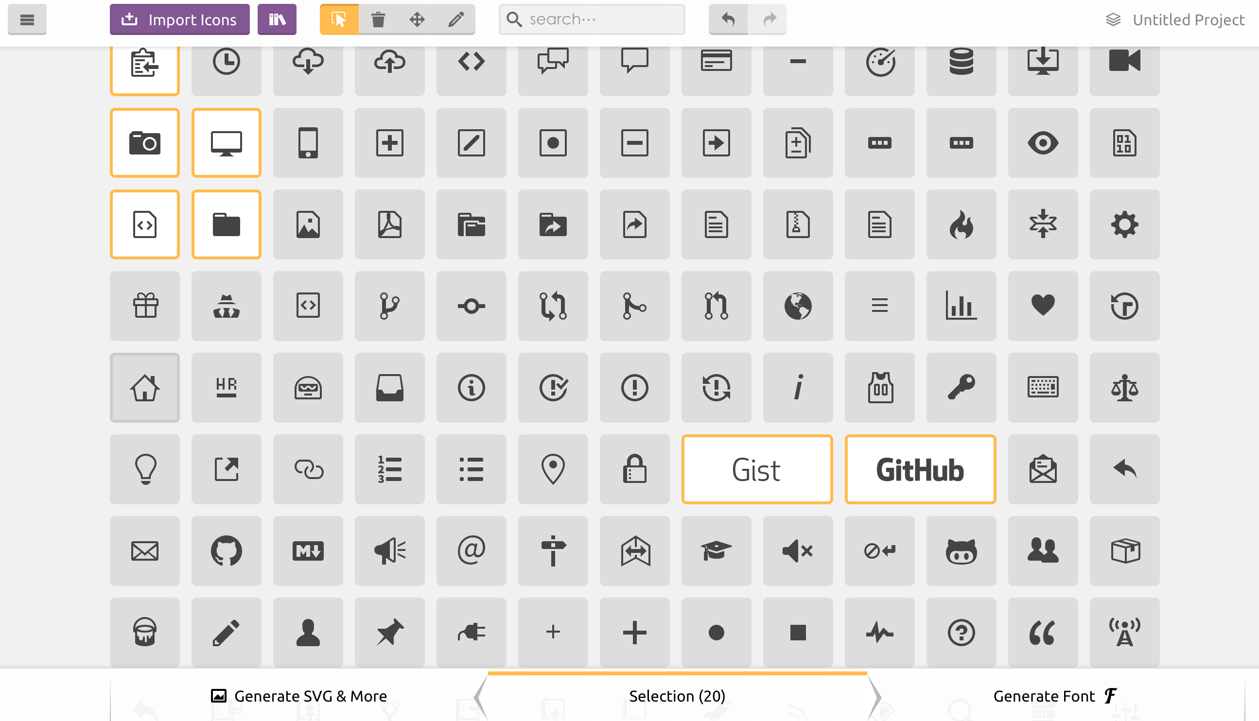
從畫面上看, 它其實很簡單操作, 選定你所需要的圖示後, 按右下角的Generate Font即可, 除了你可以自己import自己的svg檔案外, 它也提供很多付費跟免費的圖示供選用:
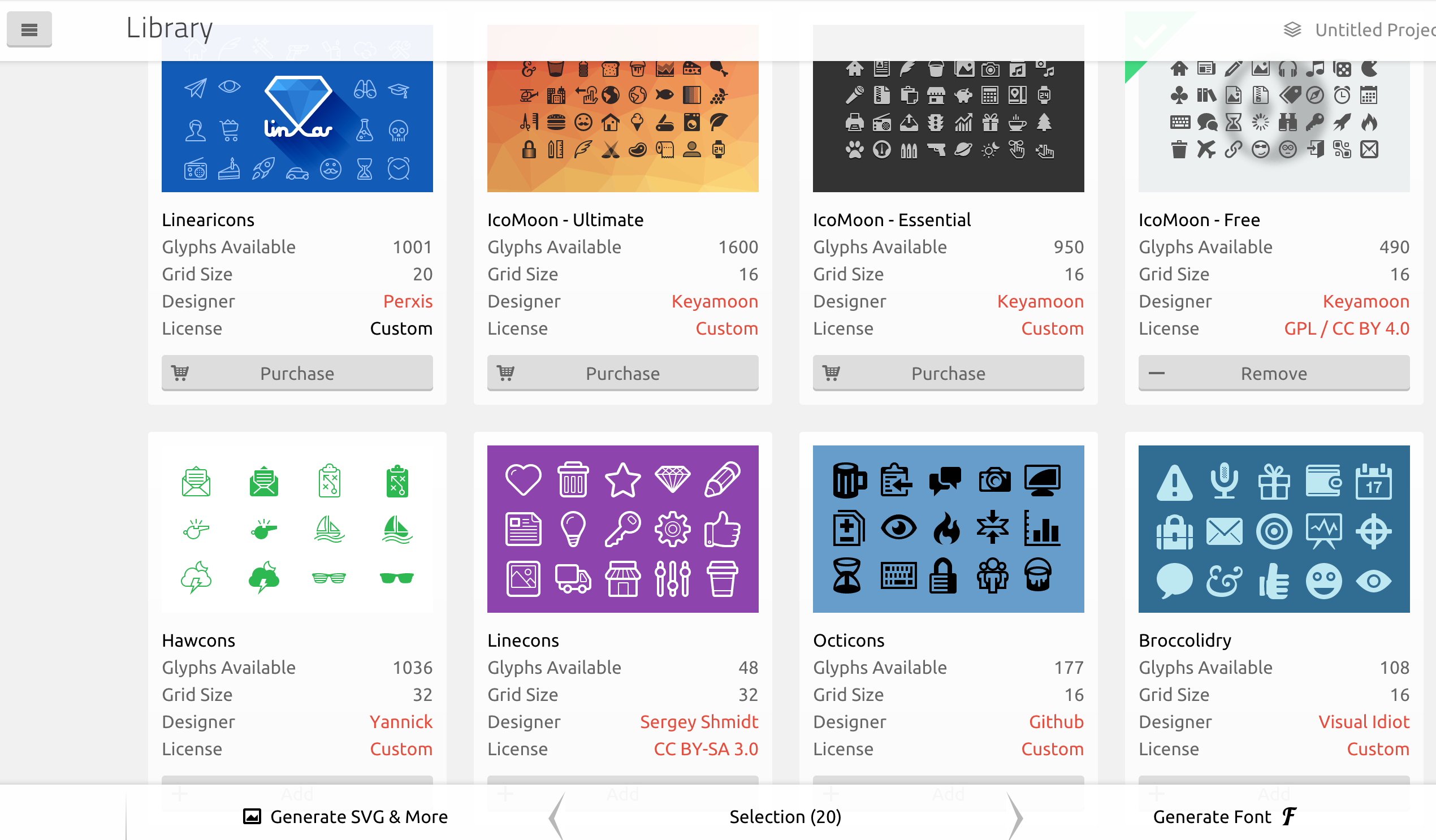
按下Generate Font後, 並不會馬上讓你下載字型回家, 它會先讓你檢視字型將會包含的圖示, 這邊有件事很重要, 左上角有個fi圖示(參照下圖), 按下去後, 下面的圖示下面會多一個fi的欄位, 這就是讓你設定這些圖示的ligature的, 如果需要一個有支援ligature的字型, 就需要去設定這邊
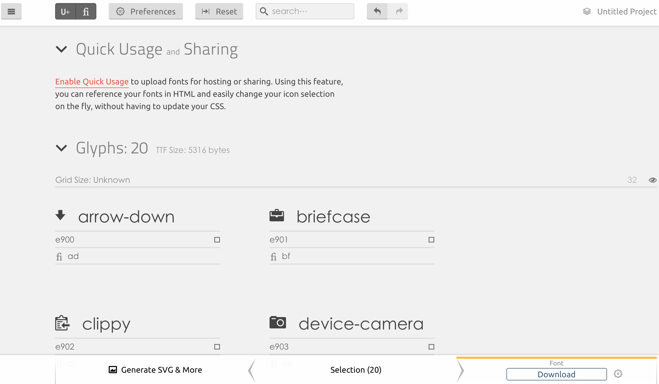
所有都沒問題後按下右下角的Download就沒問題了